Flat-Face (FF) Flange: Technical Data, Selection Standards & Engineering Application Scope
1. Product Definition
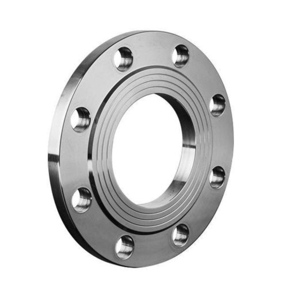
A flat-face (FF) flange is a flange style with a continuous full flat sealing surface free of raised faces (RF) or male-and-female recess profiles. Its sealing face covers the entire flange body, which requires mating exclusively with another FF counterpart.
Key Features
- Continuous full-plane sealing surface
- Full-face gaskets that replicate the full flange outline including all bolt holes are mandatory
- Uniform distribution of bolt preload across the whole flange face
Applicable Industry Standards
- ASME B16.5 / B16.47: FF face is available from Class 150 to Class 400; Class 150 is the most widely adopted rating
- EN 1092-1: Type A & Type B represent flat-face construction
- JIS B2220 (available for selected specifications only)
- GB/T 9119 (flat-face plate slip-on flange)
⚠️ Note: FF face is rarely specified for Class 300 and above per ASME B16.5, since FF sealing performs less reliably than raised face (RF) or ring-type joint (RTJ) under high-pressure service.
Our factory supplies custom-manufactured flat-face flanges upon request.
2. Core Technical Parameters
| Parameter | Typical Specification Range |
|---|---|
| Pressure Rating | Class 150 (standard), Class 300 (rare) PN6 / PN10 / PN16 (EN & GB metric standards) |
| Nominal Size | ½″ ~ 24″ (ASME inch dimension) DN15 ~ DN600 (GB/EN metric dimension) |
| Sealing Face Roughness | Ra 3.2 ~ 6.3 μm |
| Mating Rule | FF flange shall connect only with another FF flange |
| Recommended Gasket Options | Non-asbestos fiber gasket, full-face PTFE gasket, expanded graphite composite gasket, EPDM |
| Bolt Torque | 20%~30% lower than RF flanges of identical pressure class |
3. FF Flange Selection Guidelines
FF design eliminates concentrated bolt preload that causes root cracking or plastic deformation on low-strength flange components, ideal for below materials:
- Gray Cast Iron: Brittle with low tensile strength, vulnerable to localized bending stress
- Ductile Iron: Better mechanical property yet FF-to-FF joint is still preferred
- Thermoplastic Flanges (PVDF, PP, PVC): Susceptible to material creep; raised face will indent plastic substrate
- FRP Flanges: Low interlaminar shear strength, prone to delamination under concentrated compression
- Lined Flanges: Raised face geometry will damage internal anti-corrosion lining
4. Application Selection Table
| Working Condition | FF Application Advice |
|---|---|
| Cast iron valves & cast iron pump casings | Mandatory |
| PVC/PP/PVDF plastic piping systems | Mandatory |
| FRP flange connections | Mandatory |
| PTFE or rubber lined flanges | Recommended |
| Low-pressure water treatment (<1.6 MPa) | Optional |
| Low-pressure saturated steam (≤0.8 MPa) | Use cautiously (risk of gasket creep) |
| High pressure (≥Class 300 or >2.5 MPa) | Not recommended |
| High temperature >200℃ with thermal cycling | Not recommended (fast gasket relaxation) |
| Severe frequent temperature fluctuation | Not recommended |
5. Standard Specification Examples (ASME / EN / GB)
ASME B16.5 Class 150 FF
Flange, Weld Neck, 4″, Class 150, FF, ASTM A105
EN 1092-1 Type A (Flat-Face), PN16
Flange, Plate, DN100, PN16, Type A (FF), EN 1092-1, P245GH
GB/T 9119 Flat-Face Plate Slip-on Flange
Plate Flange, DN100, PN16, FF, GB/T 9119, Q235B
We specialize in custom production of flat-face flanges, welcome your customized orders.